DIY Helical Antenna For Long Range FPV
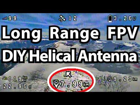
5,8GHz helical directional antenna for analog googles with 3D printed skeleton.
transcript
hi everyone today we're going to take a look at uh how i made these helico antennas these are the ones that i've used for uh oh a good majority of my uh my long range videos for the last four or five flight videos i've been using the 2rc x2 air along with one of these but uh for all my videos before the last half dozen this is what i've been using to get my range i'll uh put a couple of clips of some examples uh you know either now or right before this [Music] [Music] [Music] [Applause] [Music] [Applause] all right let's take a look at what we need to make one of these so making this antenna is actually pretty easy it's supposed to be one of the easiest ones to uh make and have work successfully uh let's quickly go through the stuff here there's soldering iron that i'm gonna use here uh you don't need anything special this you don't need a lot of heat for this um i'm gonna use a glue gun as well you could also use um probably just go to the hard store and get some you know five or ten minute epoxy that might even probably even work better than the glue gun i've also used a dremel although you could use a drill as well just to make a hole in my uh reflector here another tool is just pliers some some snips or flush cutters a knife maybe to help with getting the sheathing off of the uh the cable some tweezers and you need soldering i solder a little bit of heat shrink i just use lighter to heat my heat drink and i made my first two antennas which are the ones that the majority of my videos are been done with i used just a ruler with millimeters on it uh for the video here though i've got i got this while ago a digital caliper so we can get some more accurate measurements and unfortunately to make this really easy i'm using 3d printed parts i'm hoping that this being for fpv people that hopefully a lot of you guys will have a 3d printer or you'll have a buddy that flies fpv that can print these because these are pretty easy simple uh pla prints they don't take a long time to do we're going to use this former to wrap a coil like this for the antenna i got this off of thingiverse originally it was a little bit shorter i just made it longer because i like to make my coil a couple of wraps longer than what i want because the ends are the hardest part to get nice so i cut the ends off and use the nice middle part afterwards so this was actually two coils longer and then the frame for the antenna this just helps hold the coils to the correct spacings you could actually do this without these 3d printed parts if you had uh the right size tubing in bruce's video from rc model reviews he does a video about how to make one of these and he just uses 15 millimeter i think it's a some sort of a water water carrying tube that you could probably buy like a foot of it for a dollar at the hardware store and that's about the same size as the inside of where this is getting wrapped and if you wanted to you could go and watch bruce's video and he'll show you how to just wrap that wire and then measure out spaces onto the tube that simulate having these holes but instead you're just measuring it and then i think i think he crazy glues it or or does something to it to hold it in place on the tube afterwards at the right spacing but this one's going to be much easier because we're just using this this former and uh this frame for the antenna so it's it really makes that part quite simple there's there's no measuring to do for the actual coil dimensions all right the other stuff we're gonna need here um i've never actually bought rg402 which is what this this cable is inside i've never actually bought that and decimates and put it together and done it that way myself i've always just used a broken antennas from when i flew freestyle i'm uh running out of broken antennas because i haven't been flying freestyle lately just long range so i actually chopped off a brand new one just to have another one for the video here and the reflector here is just made out of 1 16 thick um copper clad prototype board which you can find at an electronics store or it's also on amazon i believe this is just one-sided that i'm using although i think the two-sided is a better better choice because then you can solder the coax sheath on the back side as well which really helps give it some strength whereas with the single sided you'll end up having to put a little bit of epoxy or hot glue on the back to be able to hold it securely i quickly looked up the price here for this stuff to get a uh i think it was six by six it's ten or eleven dollars canadian or seven or eight dollars u.s at a electronic shop and that gives you enough to make i think that was six by six so that was enough to make i think five of these and then the for the coil i'm using 16 gauge bare copper bus bar wire i think it was referred to and this was about 12 or 13 canadian and 10 or 11 u.s and there's probably enough for a half dozen antennas on here at least i believe for this seven coil antenna we want to cut off about 20 inches of this to have a little bit extra just to be safe and just back to the reflector now for a minute the size of this reflector should be about to be exact it's 51.7 millimeters is the minimum and if you go a little bit bigger it will just increase the side lobes on the rf pattern of the antenna and decrease the frontal gain a little bit so really for a long range antenna you're going to be best off just just go for 52 millimeters for the piece of broken antenna or if you happen to buy your own rg402 and sma and then solder them together the length for these should be for the lengths for the rg 402 you want to use either 53.1 millimeters or 70.6 millimeters or 88.3 millimeters i won't get into the reasons for using those specific lengths but if you want to understand that that's a part of bruce from rc models tutorial on this and i'll put a link to to his video below so i'm going with the 88.3 millimeter one this time because the antenna that i cut up was uh just long enough to do that because 88.3 was the feed length that the antenna i cut up was using exactly the same i actually was careful cutting the antenna apart when i was taking the antenna array off the tops that i didn't damage the sheathing so i can get a proper measurement and they were using exactly well we looked like a little bit over 88 millimeters was the measurement they used and that measurement is from where the pin comes out of the coax sheathing in the sma to where the pin comes out of the sheathing here so you're basically measuring the length of the sheathing one other thing you're going to need is an sma extension or at least that's how i've been uh attaching these to my goggles i've kind of like you could just i think go with putting an sma connector i've seen that right onto the reflector but i like putting this this piece of a broken antenna or rg 402 coax coax cable on there because then it just guides my sma extensions to be out of the way of my goggle buttons they still get in the way a little bit but uh i think it just makes it a little bit cleaner and neater i can still get to all the buttons here now the longer one goes to that side and i've actually got the the 3d model for this mount on thingiverse so i'll put a link to that below as well but it's made to fit the orcas because this specific angle and everything of the goggles the the disc thing is just fits these uh fits the 1 16 pcb or uh prototype board along with the 3d print it just fits in there nicely so to start here i'm going to measure out about 20 inches i think it was around 18 inches i ended up using but miz will cut 20 just to have a little bit extra 20 inches of the 16 gauge bare copper wire [Music] the version of this former that i did has just a little hole in the top to help hold it to get started unless you really want to try to just pull this i'm putting a lot of pressure on my thumb there i'm probably not doing the best job because of my injured finger here but don't worry it wasn't a prop accident and i'm going to stop just before i get to the end that looks like it's really holding that shape pretty nicely and the frame is gonna help it as well so this doesn't have to be perfect but the better this is done the more easily it's gonna thread into the frame so now i just cut off this little bit at the top and i can thread this up along the former a little bit i just didn't want to make the former too long so that it was ended up becoming a worry about it getting knocked over on the 3d printer if you don't have a really well calibrated printer or something yeah if you put a good pressure on that it really uh forms to it quite nicely and then just wind this off just be really gentle try not to uh damage the shape of the coil and you know obviously i've made this much longer than i needed to now i just go and cut like the first loop off the top because that's never nicely formed to the shape on the two ends let's see now with that having cut that part off it should feed through here fairly easily yeah there we go i just have to help it just a little bit at each hole i've uh before i'd started doing this i uh i printed this with supports on it and it just put supports on these and parts i've pulled those off obviously and then i just took a piece of a little short piece of wire and put it into each hole and kind of like wiggled and bent it around a bit just to get the little melted overhanging bits that were making the hole a little bit tight get those out of the way so that when you're doing this you don't want to be getting frustrated with it not fitting perfectly in the hole because you don't want this to get bent out of shape now that i've got a bit of it in there i should probably just start feeding it like spinning it from here so that i'm not bending this portion now i already did this once yesterday and wasn't happy with how it turned out so i'm i'm re re-filming this and rebuilding this antenna again i don't know why for some reason i just had a hard time with that one yesterday and uh i didn't want this to look like it's hard for you guys because it's really not i think it's just i'm struggling with my dexterity because of my injury and this is my dominant hand so it starts getting a little bit harder to feed it it's through like to keep spinning it as you get all the way in here that's another thing that uh just kind of working the wire around in those holes going through each hole before you try to do this just using a little piece of broken wire first and that will uh that'll really help making this feeding it through part easier i also i've already cut a bit of plastic away from the the base of the frame for the antenna uh let's see we you can tell here it goes through this hole and then there was one more hole where it goes really tight close down to the bottom so i just chopped that entire hole off and then a little bit of the next one i'll put some uh close-up pictures so you guys can uh can see how i did that it's getting hard to spin it on here at the end all right now i want to eyeball the last quarter of a turn out here i'm using this frame it's really easy to see that quarter of a turn so i'm just going to brace it here on this side of of the frame and bend this up to flatten out this last quarter of a turn and try to get it so that it ends up being parallel with the bottom here so you'll have spiraling spiraling down and then the last bottom quarter turn just kind of goes flat almost like as if it runs into the bottom and sitting on it although it's not going to sit on the bottom it's going to hover just a little bit above and i'm gonna leave it so that it's spiraled up just a little above a little above the bottom now with that flat part and so the coil goes through this first uh the really the hole that was really tight to the bottom that i chopped away the plastic around it goes through there and then stops oh like three or four about three millimeters away from this other former frame part here where it which i've cut just two or three millimeters of the plastic off on there uh this might be one of the harder parts of this i my carpenter so i have a jigsaw and a jigsaw just cut this out no problem it was really loud but but it worked fine and then i just sanded off the edges i think i actually used use this file that i got was like one of the frames that i ordered or something now we'll attach our rg402 or the broken antenna part to the uh just refer to this as the reflector now this this is the copper clad prototype board non-perforated just solid board you should be able to find it at electronic supply places or like an electronics hobby supply place give myself something to hold this up straight that looks almost perfect so i spent a bit of time messing around off camera there and um coming up with the a mix between soldering rolls and rolls of wire and some was trying electrical tape rolls and stuff to space underneath so the the rg 402 or the the broken antenna part the coax is coming down the middle so it's holding that perfectly there now uh so that the sheathing the end of the sheathing is like just perfectly level with the copper surface my hole i drilled here was a little bit too big so that's probably going to make this solder job a little more difficult for me but hopefully it'll be easier for you guys let me see if i can get it to settle in the center there we go now that it's in the middle of the hole it should be a little easier just having a hard time getting to stick to the sheathing in that one part but there we go so here you just want to check now that the center pin is coming up from a circle of plastic and that none of this ground sheath or the solder getting to the ground sheath is contacting the center pin because having those two stay separate is pretty vital to having your antenna work it's basically like short circuiting electronics if you let these go together so since i already tried this once uh yesterday i've already got my wave trap piece um ready oh and i think i didn't go over that one earlier the size that was the part i didn't that we need that i didn't go over so i've made this wave trap out of a piece of the prototype board this 1 16 of an inch thick prototype board it holds the now if you use the for this part you need one-sided for the wave trap so if you got two-sided for the reflector that's fine you can just kind of make sure that you remove the copper from the back side of it uh and i will i'll desolder that here so i can still uh go over that part with you but the size for this wave trap should be 6.5 millimeters by 3.2 millimeters and uh i'll put a link down below to the to a blog post by ib crazy the guy that owns video aerial systems he's the one that came up with this wave trap idea and yeah i'll put a link to his post down below if you're interested in finding out why that's there and what it's doing so that's just a piece of this copper board with uh it's just looks silver now because it's got solder all over it so we're gonna have to this is kind of a tricky part it's not hard a little bit tricky just to get this thing put in just the right place so that it's sitting in the right place in relation to our coil um the specific positioning for this uh this wave trap should be 3.2 millimeters away from this uh where this feed line comes out and i believe it's from the pin not the not the sheathing you know here's here's the easier way don't even worry about whether the wave traps in the right place just move your coil around because you're not going to attach the coil to the base here just move the coil around until it's centered over the wave trap on the on the coil and that the wave trap i think we can just eyeball this here and if you want to get really specific you can measure it out you want the wave trap to be 3.2 millimeters from the end of the coil but i'm going to eyeball it there and i can maybe snip half a millimeter off if i'm not exact enough here and all i need to do is just touch the two of them at the same time with some solder already on the on the iron and it'll connect them they both take the solder really easily and those should be connected that looks good all right now we're going to attach the antenna frame and the coil to the reflector to do this i usually just start with some crazy glue it doesn't hold very well but it at least helps provide a little bit of extra support it doesn't seem to stick very well to the copper board okay now we want to uh i'm going to position this on here so that the tip of our wire or the tip of the coil is going to come and touch that pin like you want them to you want to try to get this so they're actually touching each other because then the soldering part is going to be so much easier and i guess you also want to try to make sure you're getting as close as you can to the center of the reflector i think i'm not going to be able to get it perfect this time that's pretty close if i can deal with the pin being off sort of to the back there a little bit i've got these little i know household or kitchen clips or whatever it's going to help out with keeping it just in the right place there now we've got the frame attached to the reflector there and it's just kind of temporary there with the clips the crazy glue is not that tough but i still got my soldering iron on so i'm just going to get the last bit of soldering that needs to be done here out of the way um a little bit tight in there to get in see if i can do this and get it on camera i don't know if you guys are going to see i think that one turned out a little better now looks like it's connected to me it doesn't look like there's anything connecting the ground plane or the sheathing to the pin so i think that looks uh successful i'll uh get up another picture for you guys here or maybe i'll just wait for these for this to dry a bit and then i'll remove the clips and get a picture okay we're almost done now and i'm going to add the this is working i'm going to add glue around this edge here to help seal the antenna frame to the reflector okay we got a nice bead all the way around the edge there and i i made a mistake i forgot to slide my so much harder doing this on video i forgot to slide my bit of heat shrink over this that i wanted to put up here after i was done so here is where if you had gotten the double-sided one you would just solder the sheathing to the copper on the other side and that would give you a good connection for when you're bending this when i'm bending these i always just hold it here and then bend this part anyways let's get some glue around here to strengthen this up and if you uh didn't have a glue gun you went and got epoxy from the hardware store or something and that that'll do uh just as well or probably better i think that i should do the trick for us here now the this frames outline is 50 millimeters and i think that the best size you want to use for a minimum for the reflector is 52 millimeters so when you're putting this on if you don't get it perfectly centered on the reflector don't worry as long as you have one millimeter of reflector all the way around on on every side and then if you have more than one on another side that's okay it'll just make slightly bigger side lobes i believe in the rf pattern but as long as you're not much bigger then it should be fine you won't notice the difference so i like to cut mine to like 56 millimeters wide circles so that i have a little bit of room to play because i don't want to end up not coming far enough on one of the sides now i think the only thing left to do here is to cut off the top of our coil so this first quarter turn should go parallel with the board that's that's the way i heard it explained when i first came across it and that's the way i've been doing it so it's worked well for me like that but i've also seen them done where that first quarter turn continues on the same angle as the rest of the as the rest of the antenna but still with the wave trap on it cutting it counting my turns from where the angled part starts so just after just after this brace here and that's it it's done if your print happened to uh turn out kind of weak i've i have on some of mine put heat shrink over them just to hold the whole thing together better and it doesn't seem to have affected performance but couldn't hurt that if you had a nice clean solid print just leave it like that just get set on the goggles here just for the end so i snip this little bottom part off here i've already snipped it off i'm just gonna try to flatten it a little more this one uh part of the the brace that comes up there because then so you just need to do this if you're using this mount because then it fits nicely in this mount there we go that fits so i'm just going to bend the coax over the way i want it now okay there you go if you're using this mount with these with this 16th of an inch thick uh prototype board for the reflector and then the 3d print together just works out to fitting nice and snug so it's not going to move around too much on you so why don't you guys let me know in the comments um and ask ask as many questions as you want of course but uh yeah after you've made one and tested it out let me know if you've uh or what kind of success you've had it'd be interesting to hear how uh this goes for other people i guess there's a final note here as well when i've been using this to get my to get the really good range for my long-range flights like i think the just over eight and a half kilometers is the furthest i've been and to do that i used it wasn't these two new ones that i made but uh these two older ones that i made last year so with these two antennas i got that eight and a half kilometers so they uh they definitely work really well and that was at 800 milliwatts and uh using these two antennas together those pointed the same direction and hooked up to the best signal from each antenna and then recombining them to make the best picture possible that it can for you that's i guess the special feature of the stitching magic that uh rapid fire does thanks for watching we'll see you again soon [Music] you
- from
- Flying FPV
- added
- 2026-10-10
- likes
- 0
similar
-
Cloverleaf Antenna - Build Instructions youtube.com
5.8GHz omnidirectional antenna for analog video transmission.
-
-
-
3D Printed Drone Build - How to Wire OpenHD and Ultrasonic Abstacle Avoidance youtube.com
ultrasonic obstacle avoidance for quadcopter and OpenHD teamplay.
-
Wifibroadcast NG github.com
Use 2.4 / 5.8 GHz wifi hardware and RPIs to provide a video and telemetry downlink.
-

Flying FPV › Antennas and Trackers 📡: “5,8GHz helical directional antenna for analog googles with 3D printed skeleton.”