Cloverleaf Antenna - Build Instructions
5.8GHz omnidirectional antenna for analog video transmission.
transcript
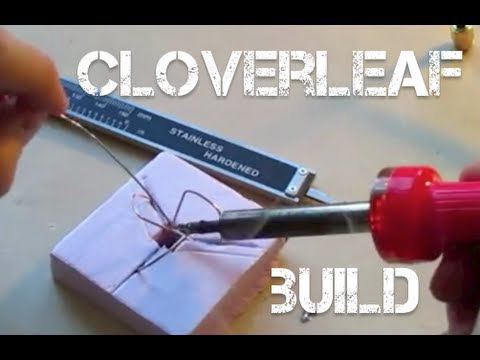
so here are the antennas that I made this is a clover leaf and this is a skew planer wheel circularly polarized antennas for my fpv video system these are for 5.8 GHz uh system and mine's from Fox Tech hobby um they're pretty easy to make and you know if you have some basic soldering skills I think that these should not be any problem for basically anyone to make so to make these you need to have have some wire I had to get this online it's Mig soldering wire it's 35,000 of an inch it's like this it's copper on the outside you need to get the cable and wire for this this is from eBay it's like Wi-Fi extension cable and you want to make sure it has this on there this type of uh connector for the foxtech system it's called an RP D SMA adapt uh connector and then it comes with some wire on there you're going to end up cutting this off just you're going to get this this is like $1.99 for one of them on uh eBay you're going to need something to measure angles with you're going to need like a pair of pliers something to strip wires with you just need like a pen some solder a soldering gun or soldering iron hot glue gun a little file to file the metal down cuz you're going to want to get exact lengths on this um I use little pink foam these little things these are like little soldering jigs that I've made I'll show you how to use this and then you need something to measure distance with or length and you need to get very very specific lengths so this is a digital uh caliper and I would really recommend using this if you're going to be making these so I'm going to show you how to make the Clover Leaf antenna which has these three wires and the other and this goes on the video transmitter on the video receiver goes the skew planer wheel which has four of these wires you build them the exact same way except you use four here and these are all at 90° angles to each other and on this one you use three wires that are at 120° Angles to each other you just do the exact same process but you just use those different angles to create these two different antennas and I'll be showing you how to make the Clover Leaf so I got instructions how to do this from the website RC explorer. and if you go on there on do-it-yourself section you can easily find the directions how to do this I've modified a little bit just to make it a little bit easier so start out with you want to cut off a chunk of this wire so careful this is wound really tightly on here and if you let it go it just will like unwind like a spring so be really careful with that so I'm just going to pull out some take my wire Cutters and snip that so I'm going to be making this for the frequency 5945 which is Channel 8 on the 5.8 GHz video system that I have so my initial cut so on this website you can actually put in the uh I'm doing that right now you can put in the frequency that you want to make it for and it tells me that I need to cut each little section of wire to 51 . 64 mm so I'm going to turn on my digital caliper here and loosen it up slide to zero zero it then move it out to 51.64 as you can see these are really really small distances so it takes a little while to get exact on here but you want to be as precise as possible to get the best video signal so now that I have this this distance in between these two uh prongs on the caliper is 51.64 so the way that I do it is I initially I kind of I set it on here I set flush to this surface and I kind of Mark just past I make it longer than it needs to be and then I take these wire cutters and I snip that off so I need to make three of these for the Clover Leaf so here are my three wires um so now I'm going to go back and measure it like this and see just how over I was so on here I notice I've got a little bit of a chunk and I just kind of eye how much I need to take off and I don't want to take off more than that but now I go back with my wire cutters and I snip off just a little bit extra there we go now I remeasure and I'm really close actually that was a pretty good snip so now comes this metal file so I take this piece now and I put on the file and I file it down just a little bit now I do it on both ends cuz it's also these Corners are kind of sharp and weird from using the wire cutter so it's a good way to kind of even them out make them easy to work with so I sand a little bit or file a little bit and then I check the distance still a little long perfect uh as you can see this wire itn't perfectly straight but it fits in there really really precisely that's yeah that's really good happy with that so now I do it for the remaining wires great so now I have my three wires at the exact same uh length for all three of them now I need to put in two 90° bends on both of them on on two on each wire so once again I go to the website I put in the frequency I'm using 5945 and tells me the bends need to be at 12.9 91 mm so here on the caliper Loos it up go to 12.91 all right now to do this I take the wire and I set one end right against here then I take my pliers these are actually uh a hospital tool but any sort of plier will work well I just like these put up against this surface now I have this then I need to do the bend get as close to 90° as you can I just kind of eyeball it it's a little much there we go so now I do it on the other side so now your wire looks like this and do this for the remaining two wires all right now all three wires of mine look the same so now you need to create a Bend you you Arc this this length right here you need to bend it so it's kind of like this so it has like a curvature to it the way that I've liked to do it and you want to make this end come around so it meets this end at like about 105° angle it says on the website so what I do so I take my tool I mean you can use pliers you can use anything here once again I latch on then I give it a slight Bend I move a little bit further along the Curve and I give it a slight Bend I'm pushing away so I'm going to do it again so as you can see I'm adding a little bit of curve in here so keep doing it so I'm going to start once you get past halfway clamp it at the other side and go like this so I keep going and just gently adding a little more and taking away till I get a nice curve curve in here and you do not want to disrupt these 90° angles on both sides as you can see here I've done my best actually yeah this is pretty well preserved on both sides the 90° angles once you add in some curve you can kind of press it with your hands so now there we go uh this is not quite 105 but if I'd make these meet down here all the way that's past 90° so I'm happy with that so you do this to your remaining two wires so here I have my three wires and they have all the bends that they need in them so the next step is to add a little bit of an angle in these so what I do is I take it and I pull the right side up a little bit so this is kind of what it looks like from head on I think you can appreciate that here this wire that coming off is higher than this one so I do it to remaining two wires now here is something that I came up with I created this little I'm calling a soldering jig and basically this is what you need your something to measure angles with these this line this line and this line there's 120 degree angle between all of these if I do that and create a hole in the middle then I took a knife and I just sliced a little slit in each of these on each of these lines so basically what I can do is I can take one end of this I can slip it right in there so I can do this for the remaining two wires there we go so that is already you can just look at that and that's really close to what this looks like already and when you're doing this as you can see if you look across the bottom of the antenna these bottom wires are all flat to each other so I don't put this these down in here too far I keep them up toward the surface so I can make sure that they're flat so I can see them in their entire length so now what I do I want to have from what I've noticed I do about a 45° angle right there so like with this wire then with this wire so I need to go up a little bit this wire definitely needs to come up so that's pretty good so now all I want to do is I'm going to just start moving these wires around back and forth until all of the the three middle wires meet if you can see that there this is actually these meet perfectly as you can see it's all they all come together in one point but if you need to do some adjustment you can pull these wires out you can bend them back and forth you can add a little more twist in there like I showed you and make that fit together but I'm actually really happy with this this worked out really really nicely and that looks just about perfect so I just turned on my soldering iron and while that's see up I'm going to set this aside and I'm going to get this wire so you got all this wire you don't need all this use it for something else I'm sure don't use this connector on here use this one looks like a mini coaxial cable so I do I go out a few inches just give myself some room to work with just in case I mess up and I just I snip it off then I take this and there's two wires in here uh and just so that they don't come apart in there cuz like the middle one can kind of slip up and down and mess up the connector down here so I take these uh forceps from the hospital and I just kind of clamp down if you have locking pliers if you've got a clamp anything uh I've noticed that this makes a huge difference cuz I definitely wasted a few of these connectors pulling the wires apart accidentally so now you want to strip off the external um coat on here and get down to the first wire here you go so now once you open it up you have this middle wire that's still insulated and you have all these fibers for right now I just kind of push them all down we'll deal with those later and then you want to strip this middle section and I like to leave uh a little bit of distance let me see I kind of measure it on here maybe like two or three millimet of this uh of the insulation on this wire I leave and then I strip off the rest there we go these external wires now you're going to want to uh arrange them you want to separate them into three groups and arrange it 120° from each other if you're making the skew planer wheel you'd want to have four groups 90° from each other here you go so now you can just kind of eyeball them uh just cuz your other angles are going to be precise on here and you'll make these fit to this so now I get out my soldering iron and it's warm yeah I'm going put a little bit of fresh solder on the tip knock off the extra and now I want to place Place one bead right in the middle where these three wires connect I want to solder them all together there so I got a nice fat bead of solder right there in the middle so I'm just going to let that cool there so I can see it's set up now so I'm just going to pull this out of the little jig I made and right here this is the hardest part and you're done with this as you can see it sits flat on the table cuz I did that on purpose like I told you guys to keep these flat you have all these angles set up and you have all of this right now so now you have this and you have this wire and if you notice you kind of set on here it matches up perfectly so you are just about home at this point you just got to take these wires I wrap it around each three of these all three of these legs and just kind of set this this middle solder joint that we've already done next to this wire so there we go now we are going to solder This Together need to solder each one of these three base wires and right in the middle so now I take a look at this and I check it is not the prettiest um but all of these are soldered on each of these three bases here this middle wire is soldered to this middle connector and there are no stray wires hanging off oh here's a few just going to pull those out cut them off we go and there's no connection between this top joint and these bottom ones as you can see that's a really nice Clover Leaf and that was pretty easy I mean that really didn't take too much time I must say the first few times I made these it was really hard and uh it definitely took me a while but now I can just fly through these things it's not that difficult at all and so now all I'm going to do is I'm going to take some of this hot glue and apply it to this middle joint and down here this does change the frequency a little bit and I've heard that will affect your range but I mean I'm already getting at least a mile on these so I uh so I'm really not too worried about that it helps just keep give this some more uh structural integrity so here's the finished product and I've got to fly with these a little bit already and for 5.8 GHz fpv video system in my experience circularly polarized antennas are the best to go with cuz 5.8 GHz gets a lot of interference and these really help resist the interference and they're pretty easy to make um I'd really like to thank RC Explorer for putting up the guide how to make these because they sell for pretty expensive online about 60 bucks a pair so you can make this with like some time and some experience you can make a pair of these pretty easily for yourself so thanks for watching
- from
- Flying FPV
- added
- 2026-10-10
- likes
- 0
similar
-
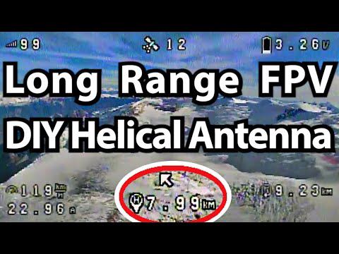
DIY Helical Antenna For Long Range FPV youtube.com
5,8GHz helical directional antenna for analog googles with 3D printed skeleton.
-
-
Wifibroadcast NG github.com
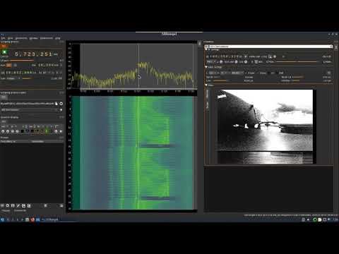
Use 2.4 / 5.8 GHz wifi hardware and RPIs to provide a video and telemetry downlink.
-
-
-

Flying FPV › Antennas and Trackers 📡: “5.8GHz omnidirectional antenna for analog video transmission.”